
Cervical Spine Sonoanatomy
Identifying the Correct Cervical Spine Level
Martinoli et al 7 first described the sonoanatomic characteristics
of C6 and C7 transverse processes (anterior and posterior tubercules). This
technique is still the most widely used to assess the cervical root level and
facilitate precise cervical nerve root injections and stellate ganglion blocks.
The transverse processes at C5, C6, and C7 have different tubercle designs, which allow for precise identification.
However, this sonographic identification technique is not the primary choice
for other cervical spine injections. Previously, we described two different
cervical sonographic identification techniques that can be used for procedures performed
in the prone position, targeting the cranio cervical junction or upper cervical
levels.1,8 Here we will review all the recommended approaches and when to use each sonographic
identification technique.
C6 and C7 Approach
This approach is applicable for patients in either the supine
or lateral decubitus position. The C6 transverse process is easily identified
in the short-axis transverse view with its characteristic sharp anterior
tubercle (Figure 2). The large anterior tubercle of C6 is referred to as the
Chassaignac tubercle. The C6 transverse process structure can be easily
differentiated from the C7 transverse process, which has a prominent posterior
tubercle with either an absent or a rudimentary anterior tubercle (Figure 3).
The vertebral artery is unprotected at this level and typically enters the transverse
process of C6. Next, the higher cervical spinal levels are identified by moving
the transducer cranially (Video 1). As the transducer position progresses
cranially, the anterior and posterior tubercles assume similar size characteristics
(Figure 4) that have been referred to as the “two-humped camel sign.”9


Occiput, C1, and C2 Approach
This approach is applicable for patients in either the prone
or lateral decubitus position. We recommend using this approach especially for
upper cervical procedures, including greater and third occipital nerve blocks,
the C1–2 joint, cervical facet injection, and cervical medial branch blocks.
The transition from the occiput to C1 and C2 can be recognized
by using either the long- or short-axis view depending on the planned
procedure. 1 We use the short-axis (transverse) view for occipital nerve blocks
and C1–2 joint injections and the long-axis view mainly for cervical facet
joints and medial branch blocks.
Long-Axis View
The transducer is applied over the midline to obtain a long-axis
view of the spine. The occiput, C1 (no or rudimentary spinous process), and C2
can be easily identified (Figure 5).

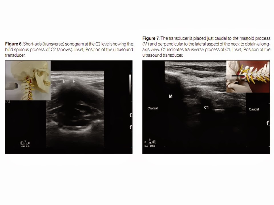
Short-Axis View
The transducer is applied over the occipital area to obtain a
short-axis view. First the occipital bone is identified, and by moving the transducer
caudally, the C1 arch is identified (Video 2) and then the first bifid spinous
process, which belongs to C2 (Figure 6). Once the C2 spinous process is identified,
the transducer is moved laterally (Video 2) to first visualize the lamina, and
then the articular pillar of C2 appears. From this position, consecutive
articular pillars can be identified by moving the transducer caudally.
Mastoid, C1, and C2 Approach
This approach is applicable only for patients in the lateral
decubitus position. We recommend using this approach especially for unilateral
upper cervical procedures, including C2–3 joint injection, cervical facet
injection, and cervical medial branch blocks. This approach was first described by Eichenberger et al 10 and later adopted by many
other investigators.
With the patient in the lateral decubitus position, the transducer
is applied just caudal to the mastoid process and perpendicular to the lateral
aspect of the neck. The mastoid process, the transverse process of C1, and the
vertebral artery will be visible in the view (Figure 7). Moving the transducer
slightly caudally, the vertebral artery can be followed as it disappears in the transverse foramen of C2 (Figure
8). Then, by moving the transducer slightly posteriorly, the first articulation
that appears in the view will be the C2–3 joint (Figure 9). From this position,
consecutive facet joints are identified by caudally moving the transducer
(Figure 10). Video 3 demonstrates the transition from the mastoid process to C1 and C2 and how to identify
the C2–3 joint.

Cervical Facet Joint Injections
Anatomy and Biomechanics of the Cervical Facet Joints
Cervical facet (zygapophyseal) joints are diarthrodial
joints formed by the superior articular process of one vertebra articulating
with the inferior articular process of the vertebrae above at the junction of
the lamina and the pedicle.
Each facet joint has a fibrous capsule and is lined by a synovial
membrane. The joint also contains varying amounts of adipose and fibrous
tissue, forming different types of synovial folds. The angulation of the facet
joint increases caudally, being about 45° superior to the transverse plane at
the upper cervical level and assuming a more vertical position at the upper
thoracic level. The superior articular process also faces more posteromedially
at the upper cervical level and changes to a more posterolateral direction at the lower cervical
level, with C6 being the most common transition level. 11,12
Excessive facet joint compression and capsular ligament
strain have been implicated in neck pain
after whiplash injury. 13 The facet joint and capsule have been shown to
contain nociceptive elements, deeming them independent pain generators. Facet
joint degeneration is more common in the elderly, and the prevalence of facetogenic
pain (pain stemming from the facet joints) in chronic neck pain has been
reported to range from 35% to 55%. 14,15
Indications for Cervical Facet Intra-articular Injections
Facet joint–mediated pain cannot be diagnosed on the basis of
only clinical examination or radiologic imaging. Cervical facet intra-articular
injections have been used in the diagnosis and management of facetogenic pain.16However,
evidence for the effectiveness of cervical facet injections in accurately
diagnosing facet joint–mediated pain is lacking. 17,18 Cervical medial branch
blocks are still considered the reference standards for diagnosing pain
stemming from the facet joints. 19
Table 1 summarizes the available literature on sonographically
guided cervical facet intra-articular injections.
Sonographically Guided Technique for Cervical Facet Intra-articular
Injections
Lateral Short-Axis Approach
We recommend this lateral approach for unilateral single-joint
injections. The patient is placed in the lateral decubitus position, and the
correct cervical level is identified as mentioned above. A high-frequency
linear transducer is used, a short-axis view is obtained, and the superior
articular and inferior articular processes forming the facet joint appear as
hyperechoic signals with the joint space in between as an anechoic gap (Figure
11). The needle is inserted into the joint space in plane from posterior to
anterior under real-time sonographic guidance.20,21


Lateral Long-Axis Approach
We recommend this lateral approach for unilateral multilevel
joint injections, as it allows for multiple facet joints to appear in the same
sonographic view. The needle is usually inserted out of plane, which results in
a shorter needle trajectory and accordingly is less painful. The patient is placed
in the lateral decubitus position, and the correct
cervical level is identified as mentioned above. A high-
frequency linear transducer is used, and a long-axis view is obtained by
placing the transducer just below the mastoid process (see “Cervical Spine
Sonoanatomy” section). The superior articular and inferior articular processes
forming the facet joint appear as hyperechoic signals with the joint space in
between as an anechoic gap (Figure 10). The nee-
dle is usually inserted into the joint space out of plane under
real-time sonographic guidance (Video 4).
Posterior Approach
We described this approach above and recommend it for few
reasons 8,22:
1. Multilevel injections can be performed with the same sonographic
view and may even use a single needle entry point.
2. Bilateral injections can be performed without the need to
change position, as the patient is in the prone position.
3. The needle is inserted in plane from a caudal to cranial direction,
which matches the caudal angulation of the cervical facet joint, making it
easier for the needle to get into the joint space atraumatically.
A longitudinal sagittal scan is obtained first at the midline
to identify the correct cervical level. The C1 spine has no or a rudimentary
spinous process, and the first identified spinous process belongs to C2 (see
above and Figure 5). A low-resolution curved transducer is usually preferred for
its larger footprint, which allows multiple levels to appear in the same view. A longitudinal scan is obtained initially
at the midline (spinous process), and then by scanning laterally, one can
easily see the lamina, and further laterally, the facet column will appear in
the image as the characteristic “saw sign” (Figure 11). To identify the lateral
border of the facet column, one can scan even more laterally until the facet
joints are no longer in the image and then
come back medially toward the joints. The inferior articular
processes of the level above and the superior articular process of the level
below appear as hyperechoic signals with the joint space in between as an
anechoic gap. The needle is then inserted inferior to the caudal end of the transducer
and advanced from caudal to cranial in plane to enter the caudal end of the
joint under real-time sonographic guidance (Figure 12). 4,22
Cervical Medial Branch (Facet Nerve) Block Injection
Anatomy of the Third Occipital Nerve
The C3 dorsal ramus divides into superficial medial and deep
medial branches. The superficial medial branch of C3, also called the third
occipital nerve, innervates the C2–3 joint and is the largest cervical medial
branch, with a mean diameter of 1.5 mm. The third occipital nerve initially
curves around the superior articular process of C3 and then progresses cranially to cross over the C2–3 facet joint
and terminates in the suboccipital region. The nerve is offset approximately 1
mm away from bony surface of the C2–3 facet joint. 23 Pain from the C2–3 facet
joint often causes cervicogenic headaches and presents with pain in the
suboccipital region. The deep medial branch progresses around the C3 articular
pillar and is involved with the C4 medial branch in providing innervation to
the C3–4 zygapophysial joint. Pain originating from the C2–3 facet joint can be
addressed by blocking the ipsilateral third occipital nerve as it crosses the
C2–3 facet joint. Pain derived from joints below C2–3 can be addressed by blocking
the cervical medial branches as they pass around the waists of the articular
pillars. 24
Anatomy of the Medial Branches Innervating the C4–C7
Facet Joints
The C4–C7 dorsal rami arise from their respective spinal nerves
and pass dorsally over the root of their corresponding transverse process. The
medial branches of the cervical dorsal rami curve medially, around the
corresponding articular pillars, and are bound to the periosteum by an investing
fascia and held in place by the tendon of the semispinalis capitis muscle. 25
The medial branches for these lower cervical levels are all so typically offset
from the bony articular pillar by approximately 1 mm. Each cervical facet joint
from C4 through C7 is innervated by two medial branches: the medial branches
originating cranially and caudally to the joint. For example the C5–6 facet
joint is
innervated by the C5 and C6 medial branches.
Sonographically Guided Third Occipital Nerve and Cervical
Medial Branch Blocks
Table 2 summarizes the available literature on sonographically
guided third occipital nerve and cervical medial branch blocks.
Sonographically Guided Technique for the Third Occipital
Nerve
We will describe a practical step-by-step approach to help perform
a precise procedure. The patient is placed in the lateral decubitus position,
and a high-frequency linear transducer is applied, just caudal to the mastoid
process and perpendicular to the lateral aspect of the neck. The mastoid
process, the transverse process of C1, and the vertebral artery will be visible in the view (Figures 7 and 8).
Moving the transducer slightly caudally, the vertebral artery can be followed
between C1 and C2 as it disappears in the transverse foramen of C2. Then, after
moving the transducer slightly posteriorly, the first articulation appearing in
the view will be the C2–3 joint (Figure 9). It appears as a convex density made
by the inferior articulate process
of C2 (cranial) and the superior articular process on C3 (caudal).
The apex of the convexity of the joint represents the joint space, and the
third occipital nerve is identified by the typical sonomorphologic appearance
of a small peripheral nerve just lateral to the C2–3 joint (Figure 13). This
target is kept in the middle of the screen, and the needle is advanced toward
the third occipital nerve usually in an out-of-plane approach (Video 5).
Sonographically Guided Technique for Cervical Medial
Branch Blocks
The patient is placed in the lateral decubitus position, and
a high-frequency linear transducer is applied longitudinally with its upper end
just below the mastoid process to obtain a longitudinal view of the cervical
spine. Once the C2–3 joint is identified as above, the transducer is slowly
moved in a caudal direction to view the lower facet joints until the desired
level of the cervical facet joint is reached (Figure 10). The highest points in
the bony reflection of the articular pillars represent the facet articulations,
and the medial branches can be visualized at the deepest point over the articular
pillars between the two articulations (Figure 10), in contrast to the third
occipital nerve, which runs over the highest point of the articulation. The
needle can be introduced into the target nerve either in plane or out of plane under real-time sonographic guidance.
It is crucial to use Doppler imaging to help identify and avoid any small
vessels, as they can otherwise be confused as the small medial branches (Figure
14).


Alternatively, once the correct level is identified, the
transducer is rotated to obtain a short-axis view, and the needle is advanced
in plane under sonographic guidance toward the articular pillar (Figure 15 and
Video 6). Then the transducer can be rotated to the longitudinal plane, as the
nerve is better visualized in this view, and the needle is adjusted as needed
to lie closer to the nerve (Video 7). 5,20
Pearls
1. The long-axis view is preferable, as having more than 1
cervical level in the view minimizes the risk of miscounting the cervical level
and can facilitate placing more than 1 needle for multiple-level injections
with the same view.
2. The long-axis view can better identify the nerves, as they
will appear in a cross section as an oval structure with the typical
sonographic appearance of a small peripheral nerve (Figure 10). This view is
particularly helpful for identifying the medial branches before
RF ablation, as this procedure requires precise needle placement
along the targeted nerve.
3. The short-axis view offers better visualization of critical
blood vessels as they course anteriorly across the articular pillar on their
way to the neuroforamen (Figure 16).
4. We recommend performing preinjection scanning in the
short-axis view to identify any blood vessels in the vicinity of the target
area, and then the needle can be placed in the same view to avoid such blood
vessels (Video 8). Afterward, a long-axis view should be obtained in an effort
to identify the actual medial branches, and the needle can be adjusted slightly
as needed.
5. Sonographic scanning before the planned procedure can
help with the diagnosis and identifying the underlying condition, eg, facet
arthritis (Figure 17) or facet joint effusion (Figure 18).
Conclusions
Sonographic guidance for the identification of cervical spinal
structures and for the performance of cervical procedures is rapidly evolving.
An in-depth understanding of sonoanatomy is critical for procedural success. It
is important for practitioners to fully understand the visualization advantages
and limitations associated with sonographically guided procedures in comparison
to fluoroscopically based techniques. Based on the promising results of
sonographically guided third occipital nerve and cervical medial branch blocks,
clinical studies are warranted to evaluate the safety and efficacy of the
sonographically guided RF technique with direct comparison to a
fluoroscopically based method. The future for sonographically guided cervical procedures
is bright, and these techniques offer many visual advantages that are not found
with fluoroscopically based techniques.
Không có nhận xét nào :
Đăng nhận xét